 Here then is the final part of this feature; I hope that it has proved to be of interest. One man's ideal is always different from another's and nearly always fascinating and instructive. I hope that you agree.
To me, solving this one was Robert’s greatest achievement. The linkage mechanism on a S2 Fulvia is really very simple. The gear lever is mounted at the bottom on an adjustable swivelling threaded shaft. A couple of inches above the mount, the lever carries a ball which locates in a nylon lined yoke. The yoke is in turn attached to a (unnecessarily heavy) steel shaft. At the end of the shaft, mounted laterally at 90 degrees is a steel cup which mates with a ball on the vertical actuating shaft on the gearbox proper; this ball is also laterally at 90 degrees to the vertical shaft. Thus, sideways movement of the lever causes the (control) shaft to rotate, lifting the actuating shaft, which selects one of the three positions or “gates” (1st and reverse, 2nd and 3rd, 4th and 5th) whilst pushing or pulling the lever selects the individual ratios. I hope you have followed this “very simple” description! Good… well now, this is all very well when the gearbox is directly in front of the driver. Pause for a moment to imagine how you are going to change gear with the gearbox behind you AND with a 1300cc V4 engine in the way!
Perhaps some of you are prototype engineers or toolmakers, with finely-equipped toolrooms at your disposal and are laughing at my description of the difficulty, but bear in mind this was largely a home operation. I suppose that a complex system of bell-cranks and levers all running in bronze bushes, with numerous rose joints could have been designed and constructed, but this would have been heavy and costly and could have ended up with almost as much slack as the steering on a V16 BRM. And perhaps Robert might have opted for a right-hand gear change that would have made routing a bit easier, but there was a better way.
After much head-scratching and consulting with MK Engineering (makers of the chassis), Robert selected the cable linkage from a Ford Focus. You will see in the pictures that he has cleverly adapted parts of the original Lancia system to their new purpose. Robert reported that this worked fine – in the fore and aft sense; all he now had to do was arrange for the up and down part; not so easy.
In fact the problem was solved by using the second cable of the Focus system acting from below on an additional piece welded to the “cup” that mates with the actuation shaft, controlled by a spring, which of course retains the gear lever in the normal position. Robert says that the gear change is smooth and positive in action.
The rest of the installation is more straightforward, but read a brief report I received from Robert:
I can't remember what stage I was at with my last update, but things are coming along fairly well at the moment. I've finished my hydraulic clutch and it works, but all the floor-mounted pedals are horrible and need modifying. Handbrake mechanism, seats, oil tank and hoses, suspension, steering, cooling system, brakes and wiring loom are nearly finished, although it’s proving tricky without a manual or any parts available off the shelf! I've also nearly finished a nice little bracket that acts as a mount between a section of the oil sump pan/crankcase and the chassis.
 Voila! Building a car from scratch is a complex business.
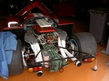
Naturally, it was necessary to fabricate all kinds of special mounts; many can be seen in the pictures. In particular, see the picture above of the very nice engine mount that Robert mentions in his report. Of course, where possible original Fulvia parts were adapted to suit. As shown in the first part of this story, the radiator is at the front, with the hot air escaping from side ducts, a simple matter of using aluminium water tubing, just like on a Lancia Montecarlo.
In England, where at least enthusiasts can still build almost any special they wish and drive it on public roads it is inevitably necessary to acquire the appropriate approvals and to meet the Ministry Construction & Use regulations. On the first attempt, the car failed its SVA test.
This was A VERY SERIOUS MATTER: the driving mirrors are required to be mounted 70 centimetres from the ground, and on Robert’s car they were… 69 centimetres! All is now well though and some testing has been done with the car being lively and with good handling characteristics. It is apparently rather noisy!
There are as I mentioned above, details to attend to. The car is to be painted – colour to be decided and Robert is seeking suitable wheels. I have been promised a ride and hope before too long to get over to England to take Robert up on the offer.
There is a grand tradition of special-building in England dating back to before the First World War. It is delightful to see that even in these over-legislated times that it is still possible to express oneself in this way (at least in some countries) and especially delightful to remind oneself of Robert’s words:
“After enjoying my Fulvia so much and succumbing to the Lancia bug, I decided to forgo a little power and 'weight ideals' and went for a Fulvia unit…”
Congratulations Robert, well done – and thanks for providing excellent material for my blog!






4 comments:
I'm really impressed by this transformation and 'out of the box' use of a 60's car engine.
The last time I have seen this was the installation of a Fulvia engine in a motorbike (pictures available on request)
Is the engine used a 1300 or 1600?
I see the used engine is 1300. The fabricated chassis would be able to cope with much more I quess. Something for the future perhaps...
It's a 1300 William; but with 500kg I should think it will be very quick
I think that, judging by Robert's questions on the Atlas forum, that aerodynamics will occupy him for the time being!
Post a Comment