Adsense

A bit of music from the lamented Radio Blog Club

Le Français

Toujours, je suis désolé pour mes amis( et amies) français(es), mais il est difficile pour moi d'écire en français. Peut-être un jour...
S.V.P. regardez ce LIEN

Wednesday, January 31, 2007

The Death of the Blog??

On this blog the writer quotes some statistics which suggest that the Blog will die.

The article is in French, but I can summarise the contents:
  • Less than one in six bloggers maintain their blogs
  • Participation: less than 2% of internet users leave comments
  • The content: often uninteresting
A study carried out in October finds that 45 - 54 year-olds and 56 -64 year-olds make up 14% and 11% respectively of total blog readership.

So CM (who writes the blog) says we must fight to keep blogs alive - write articles and leave comments!

There is then a quote from Wolinski: I will leave one of my French readers the task of translating this...

I do believe that ultimately, Blogs can only work if they become increasingly interactive; if they are consumed like fish fingers or corn flakes with nothing returned then the future seems to be bleak.

A Diversion - Especially for the Cat Lovers

Hippolyte Taine:

" J'ai beaucoup étudié les philosophes et les chats. La sagesse des chats est infiniment supérieure."

(Roughly translates as: "I have extensively studied philosophers and cats. The wisdom of cats is infinitely superior.")

An agreeable sentiment but I'm not sure that the image below supports M. Taine's hypothesis...


Source: here

A Good Idea

As a break from the Developments series, here's another development...


The late Barry Waterhouse (of Evolution Engineering) often demonstrated great creativity in solving problems connected with repairs and modifications to a variety of Lancia models.

Owners of Fulvias and of course Flavias and 2000s frequently dread the discovery of a split constant-velocity joint gaiter – a MoT/Controle Technique failure in England and elsewhere. The reason for the dread is of course the problem of removing the driveshaft to replace the gaiter, a special tool being required to unscrew the large ring nut that secures the driveshaft into the hub and of course, clamps the bearing.

Very often we came across cars that had been worked on by bodgers who, lacking the necessary tool, would somehow remove the ring nut with a large hammer and chisel and more depressingly replace it using the same method, leaving a nut that was to say the least, ugly to look at and probably not tightened sufficiently.

Given the diminishing supply of good second-hand ring nuts, familiarity with a variety of Lancia models enabled Barry to come up with a solution for the Series II Fulvias and 2000s. The Integrale and Evo models use a large hexagonal nut to secure their CV joints. This nut is substantial in construction and incorporates a built-in washer that is free to rotate thus obviating damage to the surface of the hub whilst the nut is being tightened. These nuts were readily available a couple of years ago and being fairly standard, probably still are.

Of course, it would be too much to expect the nut to be a straight fit! The CV joint thread size on an Integrale/Evo is smaller than that of the Fulvia (22mm I think); the SII Fulvia/2000 CV thread size is 25mm (at 1.5mm pitch). Examination of an Integrale nut showed that there was plenty of material to allow for a safe increase in size up to 25mm, so an appropriate tap was purchased. The nuts were bored out to 23.5mm on the lathe and then tapped to size. A check with a very large ¾ drive torque wrench showed that the nuts could be tightened to the specified value (27 - 33Mkg/ 203 – 248 lbs/ft approx) without problems.


A SII front hub, showing the special nut staked in position

Sadly, the S1 cars have a larger thread: 28mm; we were unable at the time to find a solution for this. And there is no solution for the rear hubs on either series, but of course they do not have to be removed quite so often.

At Evolution Engineering we offered the modified nuts for sale, but sold very few. I imagine that those who were wise enough to purchase them are now very pleased at the thought of being able to remove the drive shafts without the special ring nut tool – all they need is a good 36mm socket (provided of course that the CV joint splines are not tight or rusty – that’s another story). I should add that I have seen “replica” nuts nominally made to the original pattern. They were not very good – one I found would not even fit the correct tool!

Perhaps this article will encourage the more practical amongst you to try your own problem-solving; I hope so, and if you come up with something interesting, do let me know!

Tuesday, January 30, 2007

Fulvia Developments - Part V

And now the subject that I have always found so fascinating…

The Exhaust


And we thought that the Fulvia was tricky!
A 1925 supercharged 2-litre V12 GP Delage engine

The first word on this topic is: DIFFICULT

To begin with, the engine installation does not allow adequate space for the exhaust manifolding and from here on it doesn’t get any better!

The standard Fulvia manifold is a poor thing indeed. Its internal diameter at 32mm is too small; it has “blended” junctions which are not good, and it has very unequal length primaries. Matters are worse on the 1600 since the only difference is the fact that 1600 manifolds are made of stainless steel, presumably to cope with all the heat; I have seen them red hot. Incidentally, some of the replacement exhaust systems are even worse. At least the originals had proper bends. I have seen some systems where there is considerable necking at the curves; such systems are rubbish and should not be used - let alone sold; the original is already too restrictive.

Certain suppliers do offer special manifolds but I have never seen one I liked, all being more or less copies of the works ones that I have seen, which did not impress me either. Of course all offer a good improvement on the inadequate original, but they could be so much better! Whilst I was manager at Evolution Engineering in London, I organised the development of an improved manifold. At the time we had a customer who was fed up with the after market “Group IV” manifold fitted (!) to his car. It didn’t fit! I told him we could do a bit better, so we borrowed his manifold to get a basic idea of the layout and set out to produce a better one, in stainless steel. A considerable time was spent making a pattern which was then passed to a specialist company to manufacture. The enormous trouble I had with this is quite another story…

A stage in making the pattern, using a mocked-up engine and gearbox as a jig

In the end, the manifold was a success. As may be seen from the pictures, instead of blended junctions as used by the works, we incorporated collectors. It was fascinating to fit the first one to our customer’s car. The first thing we noticed was that the exhaust was quieter; I put this down to controlled expansion at the collectors. However, what gave the greatest pleasure was hearing the customer tell me about the substantial improvement in torque that the system provided, especially since this is precisely what I had forecast.

The Evolution Engineering Fulvia manifold (before the fabricators corrected the errors)

Collectors are the only proper way to join pipes

As an historical aside, some of you may remember the story of the (eventually) very successful Vanwall grand prix cars in the 1950s. They used an exhaust manifold that was pretty advanced for the time and observers remarked how quiet the cars were. The irascible Vanwall boss Tony Vandervell, loved to tease the Ferrari team with their Lancia-derived V8s, by 1957 a bit outdated. He pointed at the Ferrari exhaust pipes from which a colossal noise was emitted and joked, “That’s where your power’s going”!

When producing parts for after-market sales, one must consider the installation of the parts and so the Evolution Engineering manifold was designed to be a straightforward fit and to mate with the standard exhaust system. The enthusiast who is able to accept something more challenging in this regard has more freedom in choice of design. The picture below shows a home-made manifold that I know worked very well indeed. To fit it though, the head must be removed and the engine tilted slightly. It runs over rather than under, the left-hand driveshaft. The manifold was made by welding together numerous bends cut from spare or second-hand exhaust systems. The collectors were simple fabrications in sheet steel, whilst the flange was an original from a scrap manifold machined to accept larger primaries (35mm bore).

A very effective home-made 4/2/1 exhaust manifold featuring long primaries

Finally in this section, a few observations about manifolds. If you decide to make or perhaps specify your own, remember that the aim is to have all the primaries, i.e. the pipes that lead from the ports, equal length – with respect to the exhaust valve, so the Fulvia’s unequal length ports must be allowed for in the design. Whilst I have a four-into-one manifold on my car, a 4-2-1 is really better (with primaries 1 & 4 and 2 & 3 being coupled together of course), both for tractability and for ease of fitting. Curves should be smooth and all bends must be mandrel bends with no “necking” so often seen on poor-quality replacement systems as I remarked above. The 2-into-1 section should be of such a length so that when added to the primary length, the total is the tuned length that is to be employed. For most Fulvias I suggest something between 28 and 36 inches (71 – 91 cm). A good compromise is to make the primaries about 16”(41cm) from the exhaust valve so that the second (2-into-1 section) should be between 12 and 20 inches (30 to 50 cm.) long excluding the length of the collectors. Collectors should be constructed with their sides at an included angle of around 14 degrees and it is essential that the pipes are cut off cleanly where they enter the collector – it is even better to have a tapering “tongue” that enters the collector but this is tricky to make). Internal diameter of the primaries should be 1 3/8” (35mm) and of the secondaries 1 1/2” (38mm). In a perfect world, the length of the single pipe which follows the 2-into-1 collector, should be the tuned length when it meets the silencer. This is usually impossible on a Fulvia for clearance reasons. Perfectionists could employ a small expansion chamber here… The internal diameter of the single pipe should be 2” (51mm) or perhaps a little more.

I make no excuse for writing at length on this subject, which really deserves at least another 1000 words! I believe the exhaust to be critical in getting the best from an engine and given the inadequacy of the standard arrangement on the Fulvia, something that should be dealt with as a priority even if it is difficult and expensive.


Next time, I take a look at the fuel system

Monday, January 29, 2007

Whoops!

Apologies for the triplication in my last Developments piece - and thanks to William for pointing it out. I have now edited it.

And sorry to Matt fans - to paraphrase Rear-Admiral Sir David Beatty, there seems to seems to be something wrong with the bloody Daily Telegraph today!

Saturday, January 27, 2007

Fulvia Developments - Part IV

I finished the last part talking about valves; now I will have a look at the valve gear


Valve gear

A valve spring has a tough job - especially at high speed. Not only does it have to lift its valve up very rapidly and of course, repeatedly, but it also has to lift the rocker. We cannot do anything about the valve (without resorting to titanium for the inlets) so what about the rocker? Reducing reciprocating weight makes life easier for the spring and will raise the engine speed point at which valve float occurs.

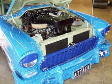
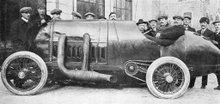
Remove a tappet screw from a Fulvia rocker and you will usually find that the threaded hole is not in the centre, meaning that there is a lump of useless metal flapping up and down at the end of the rocker where the reciprocating weight is greatest because of the length. Rockers can be dramatically lightened. There is no point in working hard on the pivot point where the rocker runs on the shaft, since there is no significant reciprocating effect there. And no metal should be removed that reduces the height of the rocker. Have a look at the rockers on the high-performance American V8 engine in the picture – the upper and lower edges are almost but not quite, sharp; there is no surplus metal and they are a good indicator of what a rocker should look like.

A very “hot” Chrysler “hemi” installed in an American dragster

source: Petersen’s Hot Rod series: "Cams, Valves, Exhaust Systems”

I spent a long time with Swiss files on my rockers reducing their weight. I then polished them with abrasive paper and had them shot-peened – I consider this essential for rockers that have been modified since they are forged components, and lightening and/or polishing removes the tough “skin” on the surface which must be replaced by peening (those who like the idea of polishing con-rods might care to consider this point).

Those with 1300 engines should try to find a set of 1600-type valve caps; these were drilled and thus lighter. Alternatively, titanium caps are available from Huib at Viva-Lancia.com.

Fulvia engines are old, the years do take their toll; this is very noticeable in the valve gear. Tappet screws become “mushroomed” at the ends, depressions appear in the tops of valves and needle tappets, and the hardened pads on the rockers that run on the camshafts also wear. Some of these problems can be addressed: the screws and rocker pads can be reground to shape, but I have no easy suggestion concerning the rocker shafts; these wear quite badly. They are made of material which is very hard or I should say, heat-treated for hardness. It is probably possible to have them chromed back to size and centreless-ground, which would be costly but probably not as expensive as having new ones made from scratch.

The only satisfactory solution for the valves is to replace them. In any case, the valves fitted to 1300s were not of the highest quality although quite satisfactory in normal use but perhaps not with unleaded fuel. Modern valves are generally made from 21/4N (I do not know the European Standard designation) an austenitic stainless steel specially developed for valves. The original exhaust valves fitted to 1600s were made of an exotic material, Nimonic 80, an alloy that has very little iron in its composition; it is mostly composed of chromium and nickel. Henry Wiggins & Co in England developed the “Nimonic” series of “Super Alloys” during the Second World War for use as turbine blades in jet engines. 21/4N is a perfectly good substitute and quite possibly better for exhaust valves. The first recorded use of this material for exhaust valves that I have been able to find was in the Coventry-Climax F1 V8 engine of 1962.

There are materials that are even superior to 21/4N but I cannot imagine that they are necessary in a Fulvia.

Because of the high contact loads applied to the tops of the valves by the small tappet screws, a very hard tip must be added. This is usually achieved by friction welding. The hardness should exceed 60 Rockwell “C”. The tips are usually made from some sort of high-grade tool steel.

Since the Fulvia uses bronze valve guides, it is not necessary that the valve stems be chromium-plated.

A set of valve guides prepared for a Fulvia.
Note the taper on the inlet guides to improve flow, whilst
The exhaust guides are left straight to help them cope with the heat

Series 1 Fulvias used valve guides that did not have valve stem oil seals and there is no provision for them, whilst Series 2 cars did. I imagine that the S1 guides were especially finely honed. The best material for guides is nickel-silicon bronze; one trade name for this material is “Colsibro” and at one time at Evolution Engineering we used to make our guides from Colsibro bar. Later for the Fulvias, we bought valve guides specified for the Mercedes-Benz 190 Cosworth 16V. These are perfect for the Fulvia, having a safety spring clip and being made from the correct type of bronze. However we had to machine them to accept the normal valve stem oil seals as the Mercedes-Benz ones were a different pattern.

Finally we used to modify Lancia 16V guides (see picture above). Once again they are the correct material and accept the oil seals. Incidentally do not use the seals normally supplied in the Fulvia gasket sets. Use Integrale or Thema ones or similar. These are made of silicone rubber and do not harden with age unlike those normally supplied. I never fit seals to the exhaust valve guides as I consider it unnecessary and a little oil is probably a good thing for such hard-working components.

Camshafts

The standard 1.3S/1.3HF/1.6HF camshaft (all the same) offers 56 degrees of overlap and duration of 274 degrees. In many engines of the period, this would have been considered a high performance specification for a road car - even a bit “wild”. I have found that in modified engines the original camshafts work very well indeed; various suppliers offer different Fulvia profiles but I would consider the camshafts the last thing to change in a development programme. For more information, see “Fulvia Thoughts 5” on this blog.

Next time, The Exhaust

Thursday, January 25, 2007

Fulvia Developments - Part III

Some Development Ideas

Having outlined some of the limitations of the design in my two previous articles, I will now offer some suggestions as to how the performance of the Fulvia may be improved. These are based almost entirely on experience of modifying Fulvias on a restricted budget; I have not had the opportunity of tackling a “carte-blanche” project!

Before I begin I should like to set some terms of reference. These ideas and suggestions will be general rather than very specific. Every engine has its own requirements in such areas as fuelling, ignition and cam timing.

Cylinder Head

A gas-flowed 1300 Fulvia head – note the dowels to locate the manifold accurately

As with almost any engine, one should start with the cylinder head. The original fit and finish on the head and its associated components is not perfect – more so on S2s than on S1s of course. All the normal procedures apply and I expect that to many of you they are well known.

Match the inlet manifold to the head and dowel it to ensure accurate repeat fitting. Match the carburettor mounting rubbers also; there is usually a nasty “step” at this point.

Gas flowing a Fulvia is a tough business, first because of the two long ports on each side and second because of the hard, high-quality aluminium alloy used. The usual method requires the use of a good die-grinder with a long “snout” that will allow full access. Tungsten carbide burrs can be used – with care – to “rough out” the valve throats, flap wheels of 60 grit are used for the ports and for the throats but these have to be reduced in diameter before they will enter the ports. A “split stick” with 150-grit paper is used for finishing. Normal practice on the inlet side is to work at the ports until their diameter is about 85% of the inlet valve diameter. This is possible on a Fulvia with standard size valves or even slightly bigger ones. I normally remove all of the boss around the valve guides although one experimental head I did featured a modified boss on the inlet side to provide a “twist” to the incoming charge to ensure better homogeneity of the mixture. I understand it works quite well. Either way, the principal result of this work is greatly improved torque – and I am convinced that much of the benefit comes from the exhaust side. Considerable improvement can be made to the inlet manifold by careful attention. In general I recommend that anyone who fancies trying gas flowing should a) practise on a scrap head and b) read a decent textbook about gas flowing theory – actually in reverse order!

The valve seats should be cut to three angles – for the valve seat itself I prefer 45 degrees to the 30 degrees found on 1300 inlet valves and on both valves on the 1600. A radiused seat is better still (inlets only) and the exhaust seat should be about 1.5mm wide, no more. On standard heads, the seat area can always be considerably opened up greatly improving flow. The inlet seat should be on the edge of the valve and 1mm wide. Careful work on port matching and valve seats and throats probably yields about 75% of the improvement obtained from a full gas flow job.

Seat cutting with a Serdi machine

Larger valves can of course be fitted, but not much larger without drastic changes by which I mean enlarged inlet valve seats. It is a simple job to use 1600 valves in a 1300 head, but of course this represents only a 5.8% increase in valve area; on the other hand every little bit helps.

Important: if you fit larger valves then it is necessary to enlarge the cut-outs in the piston crowns; failure to do this (certainly on 1600s) will result in bent valves and damaged pistons. I have a good procedure for doing this – contact me for details.

Remember that if much larger valves are to be used, the seats will have to be cut deeper and this will mean that the installed height of the valves will be incorrect leading to possible valve float problems unless the valves are correctly specified. Small changes may be corrected with hard washers under the springs. It is however, debatable whether, with the limited port size, any significant benefit will be obtained. In my own engine I have 39.5mm inlet valves and 37mm exhaust valves. The exhaust valves were really a whim as I had some good quality austenitic stainless 1300S inlet valves available and just decided to give the idea a try. Luckily (as it was rather a one-way operation) I detected a small increase in torque in the mid-range and that was it – no money for dyno sessions at the time!

Next time: a look at the valve gear

Something Strange

Nikola Tesla was an extraordinary man.

Amongst his many inventions was the Coil that bears his name. Building and playing with these is a popular hobby - especially in the U.S.A.

I think that the results are splendid.

Source not known - found years ago in Google Search
Will acknowledge if source comes forward

Wednesday, January 24, 2007

Fulvia Devlopments - Part II

Part II of the series looks at some details of limitations of the Fulvia engine.

A Variante 1016 engine. Photo: Gustav Drake

Over the years, I have thought a great deal about the difficulties associated with developing the Fulvia’s engine but I still do not have the full answer (or anything like it) although I do have a few ideas.

To me the key word (or rather, words) is volumetric efficiency. One clue is that whilst the 1600 would obviously provide more torque by virtue of its capacity, it seems that developers could get substantially better specific outputs from the 1300. There are two factors here: one is valve sizes – and the other, port sizes.

The standard valve size on the 1300S engine is 37mm for the inlets and 33mm for the exhausts. The 1600’s valves are only 1mm bigger. Now, consider the difference in capacity: the 1600 is 22% larger. A couple of minutes with the calculator shows that the 1600’s valve area is only 5.8% greater than the 1300’s. Now I am not suggesting that the valve area should be 22% greater for the 1600, as the greater depression will of course pull more air through a given aperture. Still, 5.8% seems a bit mean. Four-cylinder engines of similar capacity and of the high-performance type would typically have inlet valves of 41mm and exhaust valves of 38mm, perhaps more. And of course this is not the end of the story: there are the ports to consider. Apart from the fact that the internal water passages limit considerably the opening up of the ports, there is what I call the “No 4 exhaust port problem”. Straddling No 4 exhaust port are the two right-hand rear cylinder head bolts. They are just 36mm apart centre to centre. For a performance engine it is generally considered that the exhaust port diameter should be the same size – or greater than – the exhaust valve diameter, obviously impossible. On the 1600 head, about 33mm is the limit and even this can be a problem sometimes, it being quite normal to break through the port wall where the bolts are.

From the above it should be apparent that there is a built-in advantage with the 1300 engine in volumetric efficiency terms, since the ports and valves are virtually the same size as those on the 1600 – for 22% less capacity - and there are other factors too.

I have no mathematical pretensions, but I do know that good balance in an engine is influenced both by engine speed and by the weight of the reciprocating parts – the lower the better. In the case of the Fulvia, there are probably additional factors: the engine architecture (crankshaft centre line is not at the apex of the V, although this is probably necessary) bore/stroke ratio, con-rod/stroke ratio (large on the Fulvia and generally seen to be a good thing) V-angle and so on. What is undeniable is that the smaller Fulvias are definitely smoother, with a good 1200 being almost turbine-like. Perhaps this is one of the reasons why the tuners can get the 1300 to buzz up so readily?

Other influences include pumping losses (the breathing arrangements are poor) and frictional losses – due to crankcase distortion and other matters associated with the architecture. Finally, two important factors both entirely due to the strange (and actually unnecessary) idea of installing the engine at 45 degrees: the nasty curve in the inlet manifold, together with its unequal length passages, and the limited space for a proper exhaust manifold.

How it began: Fulvia berlines at Fulvia 40 in Turin in the evening

In Part III, I will offer some development ideas. Let's have some comments!

Tuesday, January 23, 2007

Another for the Cat-Lovers

" L'intelligence chez le chat est sous-estimée." Anonyme

"The intelligence of the cat is under-estimated." Anonymous

"Another gas-flowing job? - Me? - Not likely!"
Source: Simi


Fulvia Developments: A New Series of Articles

Bonjour, good morning/ afternoon to all.

Here is the first part of a series that I have been writing over the past couple of weeks. I expect that some of the content may be disputed or even controversial, so be it - I await comments, criticism etc. as usual. I also await your custom!
***************************

Fulvia Engine Developments

Part I

Background and General Considerations

Gas-flowing: the early stages

Over the years, I have been asked many times about increasing the power output from the Fulvia engine. I usually point out that there is no simple route, for reasons I shall try to explain later in this series of articles.

In fact in standard form, the Fulvia was remarkably powerful in its time – that is in specific terms, with roughly 70 hp per litre; few of the Fulvia’s contemporaries could boast such efficiency. I well recall my amazement when, driving with two friends in my first 1300 S2 coupe at 100 mph, I was able to converse without shouting! I sometimes think that for those who use their Fulvias only as road cars, pursuit of extra power is rather pointless. After all, the process is very labour-intensive and consequently expensive and naturally the car’s character will change. I have also observed that efforts to improve the driver’s performance could be cheaper and more effective; a Fulvia in the right hands is still quick today from A to B. And as standard and in good order, it is a lovely car.

Nevertheless, there are always those who wish to develop the car either for the sheer hell of it or for competition purposes and it is these to whom this article – or rather, series of articles – is addressed.

**************************

Before examining the Fulvia I would ask you to consider the engine in the old Mini. Here we have a cast-iron motor that can trace its origins back to about 1948 or perhaps even pre-war. It has vertical valves side-by-side in its cast-iron head, long push rods, long stroke (except for the 970 and 1071 “S” cars) two siamesed inlet ports and three exhaust ports, with cylinders 2 and 3 having to share the middle port. Read any engine theory book and you will see that theoretically this recipe is hardly promising. Despite this, a number of tuners have obtained more than 100hp/litre from this engine in various sizes, running at around 8000 rpm and this was some years ago; they are probably doing even better now.

Very well, let’s consider the Fulvia’s engine: short stroke, twin overhead camshafts, valves inclined at 60 degrees included angle, light valve gear, nicely shaped combustion chambers (similar to Porsche 911) one carburettor choke per cylinder, aluminium cylinder head, high compression and so on. And unlike so many production engines, there is a fully counter-balanced steel crankshaft, forged rods and rockers etc. One could be forgiven for thinking that the sky’s the limit. Sadly this appears not to be so. Here are some horsepower figures:

Works Gr IV 1600 Rally car 1972/3: 1599* cc – 158hp

Special prototype 1300 engine – 143hp†

*Works cars were generally bored to 82.4mm

Quoted in “Lancia Racing” by Nigel Trow

I should add that I have been told by someone who claimed to have seen the factory papers that in fact Lancia never got more than 150hp from their 1600cc rally cars. And I am sure that the special 1300 engine mentioned above was very much a one-off. And the same source told me that he had it on good authority that quite frequently at the factory in the old days there would be an explosion from the test house quickly followed by a number of excited Italians running out… The problems of trying to get big power from a Fulvia…

Two more Fulvia examples:

1300 Sport Competizione (owned by Carlo Stella)

This car was extensively developed in 1972 by Baggioli and Gottfredi and is fitted with Kugelfischer fuel-injection (See Stella’s book on the Competiziones).
It develops “around 144hp” at 8500 rpm (111 hp/litre)

Finally, my own car developed with no money of course!
1599cc, 11.5/1 compression, special camshafts, big valves, Lucas fuel-injection, special exhaust etc.; about 145-150hp at 6700rpm (90.6 – 93.8hp/litre). I should add it would probably be a bit better if I had the time and money to calibrate the injection, make a new exhaust system etc.

I mentioned the Mini engine above; here’s another period competitor:

A very powerful FIAT 128 engine with Kugelfischer injection

Source: “FIAT 128 La Storia etc.” pub. Sileagrafiche

FIAT 128. 1300 c.c. single overhead camshaft, wedge-shaped combustion chambers, cylinder dimensions 86 x 55mm. Italian tuners such as Trivellato extracted up to 160hp (123 hp/litre) from this engine, which would run at 9,000 rpm with its standard cast-iron crankshaft and over 10,000 with a steel one. Incidentally at high revs they sound glorious!

*******************

Next time: A detailed look at some of the limiting factors (from a developmental point of view) of the Fulvia design


Sunday, January 21, 2007

Trip to the Jura - Part II

Here then is the second and final instalment of my report on the Jura trip.


Gearbox

With the engine out of the way, the next task was the gearbox input bearing. It must be said that this is one of the weaker points in the Fulvia’s design and I suppose in this instance, it is Luigi Bosco, designer of the Fulvia’s gearbox who must be held responsible! Indeed the earlier gearboxes, fitted to 1200 sedans and some coupes had an even less adequate arrangement, with a shorter roller race and only one oil seal. Obviously this must have given trouble as a longer bearing and an extra seal were added (an arrangement that still gives trouble hence this section!); I believe that the changeover came at the time of the introduction of the 1300 engine, but I have no easy way of checking this.

After removal of the quill shaft: note the oil in the bell housing

First it was necessary to remove the bell housing from the gearbox; this requires beforehand, the removal of the quill shaft, which in turn requires removal of the rear cover of the gearbox, WHICH in turn requires the removal of the rear sub-frame cross member. Not altogether a five-minute job! And since someone had fitted the cross member upside-down, I had to remove the gearbox mounting rubber too. In the end of the gearbox mainshaft you will find a circlip which retains a small steel disc. This covers the end of the quill shaft. A sharp shove on the shaft at the clutch end will expose a circular spring ring on the shaft (at the other end!). When this has been removed, the shaft can be extracted, from the front of course.

The bearing and one of the seals are contained in a steel tubular housing which is a tight fit into the bell housing casting and which are retained in position by means of a spring clip with a “tongue” which passes into a hole bored into the side of the steel insert. The second oil seal is fitted into the bell housing itself, directly below the steel tubular insert. After the spring is removed, the steel insert can be easily extracted, but removal of the seal in the bell housing is a pain: there is no “shoulder” to act upon and in this instance the only way to remove the seal was effectively to destroy it taking care not to damage the bell housing itself. The picture shows some of the parts: the steel housing with the bearing and one of the seals, with the retaining ring next to it. The second seal, and afterwards, the steel housing are mounted in the centre indicated by the red arrow in the picture. The groove in which the retaining spring ring fits may be seen on the exterior of the boss.


Bell housing on the bench for bearing and seal replacement

After pressing in the new bearing and seal into the steel housing and fitting the bell housing seal, the next job is to refit the steel part to the bell housing. It is of course essential that the holes for the spring clip – in the boss and the steel housing - are exactly aligned as there is not really a second chance, because removal of the housing usually results in damage either to the bearing or to the seals. I find it helpful to draw a line of the bell housing to show the position of the hole. In this case all went well.

Before refitting the quill shaft, I used it as the perfect clutch alignment tool, having already fitted the drastically lightened flywheel.


Clutch fitting using quill shaft for alignment

Driveshafts

With the inner pot-joints (S1s and Flavias only) being secured to the gearbox output flanges, by six set screws, each “squeezed” between the flanges and the ‘box casing, removal of the shafts with the engine in place is a miserable business, especially as the area is normally remarkably filthy. However I was lucky to be working on a clean car with the engine removed. Of course I have the appropriate special tools to undo the ring nuts that secure the outer CV joint; a complex and typically thorough Lancia job on S1s with the inner ring nut (torqued to about 225 lbs/ft – 300NM) the tongued vernier lock ring with its little dowel and finally the outer staked ring nut; it is impossible to imagine this lot ever coming loose. Incidentally this is not unknown on S2s resulting in an intermittent long brake pedal and sometimes, ruined bearings and hubs.

I found that the outer CV joints would not come off the shafts, perhaps through previous damage to the circlips, but the inner ones came off easily albeit with a large quantity of horrid black gloop! All CV joints were in excellent condition with no detectable play whatsoever.

Sub-frame Assembly

Having found loose nuts and bolts in various places, I checked those that were accessible on the sub-frame – again a good idea since the four long 8mm bolts and nuts that retain the front spring were really very loose, and someone had omitted to fold over the tab washers that lock the four short lateral bolts. After correcting these lacunae, it was time to refit the engine.

I cannot remember ever having an engine go back in so easily – it just slid in to engagement with the gearbox almost by itself – demonstrating the importance of slinging the unit carefully to ensure the correct angle.


The engine went in like a dream - I was smiling more a couple of minutes later!

As there was a compression tester available I carried out some cold compression tests, first “dry” and then with a little oil added to each cylinder; this normally shows up ring sealing problems. There was indeed a great difference between the two sets of figures – something like 105lbs/sq in (7 bar) dry and 180 lbs/sq in (12 bar) with oil added. I concluded that there were problems with the piston rings.

On starting the engine I was amazed how nicely it ran – with the oily exhaust port and compression test results I had expected smoke and uneven running, but the motor ran like a sewing machine. And the subsequent road test showed good power and smoothness and again no smoke. I hate to have to admit this but this is a complete mystery to me. The owner confirmed that the car made smoke but it no longer does! And when switched off, the engine stops almost instantly – partially due of course to the light flywheel but also to good compression.


Rear Hub Bearings

The owner had wisely acquired some good stripped rear hubs – I do not own the tool to remove the outer bearing retaining ring nut and in any case, two weeks’ soaking in oil and a ¾ impact gun are usually necessary.

However, I had detected no bearing noise during the road tests, and checking showed that the bearings were perfect; just a faint noise probably from the handbrake pads. The owner expressed his opinion of the CT/MoT man in very “full and frank” language!

With nothing left to do, we set out on a more extended road test. Once again the car ran perfectly, with zero smoke and encouragingly good oil pressure. I was able to drive also and enjoyed every minute; a really good S1 is a true epicurean delight.


A small break on our road test

One can only feel sorry for those who have not had the opportunity to appreciate such an excellent car.

I believe that on departing I left behind me a pretty satisfied customer!

Contact me if I can help with your Fulvia - VAR1016@gmail.com

Saturday, January 20, 2007

Trip to the Jura - Part I

I promised a report on my work last week. Here's the first part.

The Jura: a lovely part of the world

Over the years, more or less since I started contributing to the Viva Lancia forum, I have received quite a large number of enquiries from Fulvia owners around the world with questions on a considerable variety of topics related to our favourite car. And I have received quite a few more since starting this blog.

From this, I have received a certain amount of work. My latest client contacted me in connexion with his 1970 S1 Fulvia Sport 1.3S.

After the usual discussion, he retained me to do the following:

  • Remove engine
  • Fit lightened flywheel and new clutch plate (parts to be supplied by client)
  • Remove sump to check bearings (he was concerned about low oil pressure)
  • Check oil pump
  • Renew gearbox input shaft bearing and oil seals (I had seen the oil collected in the bell housing in a photograph he supplied)
  • Renew all drive shaft gaiters
  • Renew rear hub bearings (advised by MoT/CT man that one of these was noisy)
  • Finally, to assess the car in general (the engine was reportedly smoky) and also provide a degree of instruction in Fulvia maintenance generally.

The work was to be carried out at the client’s house in the delightful Jura region of France. For those who are unfamiliar with France, the Jura is roughly speaking, that part which borders Switzerland north of Geneva.

On arrival I found that my customer lived in a most attractive house that, like much of the rest of the small town where it was, originated in the late 17th century.

The car was obviously in very good general order having been restored some years before it was acquired by the present owner. The restoration had been extensive, with a fine finish on the sub-frame and its cross members, suspension components etc. Encouragingly for a S1, the brake fluid was very clean indeed!

It was some time since I had last worked on a Zagato Fulvia, and I had forgotten just how cramped the engine bay is compared with a coupe. Nevertheless the engine came out easily enough (about an hour and three-quarters). I had not been able to hear the engine running as the owner had already drained the fluids and removed some hoses.

The first thing I noticed was the very oily No 3 exhaust port – examination of the plug showed signs of oil deposits. There was not time to remove the head to try to establish the nature of the problem, but more on this later…

Engine out: note the oily No 3 port

After removing the clutch and flywheel, I removed the sump in order to have a look at the bearings. First I removed the oil pick-up pipe so that I could remove the centre main cap and inspect the frequently troublesome centre main bearing. This I did and found that the bearing was in nearly new condition, as was the centre main journal. The crankshaft had been reground as examination of the bearing shell confirmed. I replaced the cap and then removed the cap of No 2 big end. Same story here; there was no need to remove the other caps – when a Fulvia has bearing trouble, nine times out of ten the problems concern the centre main and/or Nos 2 and 3 big-ends.

It was at this point that I came across the first problem. On attempting to refit the oil pick-up pipe, I found a fault that is depressingly common on Fulvias: one of the threads in the engine front plate where the pipe connects to the pump feed gallery was damaged – in fact there was hardly any thread remaining. Fortunately it was the lower of the two and thus not partially obstructed by the first main bearing cap. I was able to drill out the hole and tap to M8. Then it was simple matter of boring out the mounting hole on the pick-up and fitting it with an 8mm cap screw. I always use “Loctite” on these screws: after all, air is a very poor lubricant! When fitting oil pick-ups to Fulvias there is only one correct way: fit each screw loosely and ensure that all are correctly started before tightening; in this way the risk of thread damage due to misalignment is minimised.

After refitting the sump, I removed the oil pump, first of course loosening the adjacent front plate mounting bolts – otherwise it is usually impossible to extract the pump. Upon dismantling it was apparent where the oil pressure problems originated: the pump was very worn. Measurement of the rotor clearance showed it to be about 0.25mm – 0.010” whilst the factory specified a maximum clearance of half this figure. A friend of the customer came up with a used pump that, whilst out of specification too, was distinctly better. I refaced the cap of the replacement pump using an oil stone – a mellow half an hour or so…

Lubrication System info. From Lancia Concise Shop Manual

I decided that it would be a good idea to check the tightness of the various bolts around the engine, and it was just as well. First I found that a variety of different specification bolts had been used for the all-important block to crankcase joint. For 1300s these should be “10” grade as marked on the bolt head (12 on 1600s). We found that some of the correct bolts had been distributed around the engine in various non-critical applications. And worse, the bolts had not been properly tightened. If these are really loose the result is disastrous, with enormous oil leaks, dreadful noises and all sorts of horrible consequences – including having to dismantle the engine to renew the gasket. After all had been correctly torqued (necessitating removal of the dynamo and engine support bracket) the head bolts were checked and the tappet clearances set.

To be concluded

Rallye Monte Carlo

It is wonderful how close to the action one can get in a World Championship event.

The picture shows Dani Sordo working hard in chasing his team mate...

I await Lancia's return...

Thursday, January 18, 2007

Thrills and Spills

Today I am off to have a look at Loeb,Gronholm & Co in action down in the Ardêche; yes it's the Rallye Monte Carlo.

When I come back I'll start posting some new stuff here; meanwhile here's your happy mechanicen in action...


Photo: Thomas

Wednesday, January 17, 2007

More on the Mid-Engined Special

You will recall that in the last piece on this car, I congratulated Robert on a job well done.

In the piece I also remarked that there was some finishing to do...

More than some! Robert has taken my advice and subscribed to Atlas

If you go to this thread in the technical forum, you will see that Robert (aka "Robroy") is very serious indeed. If he continues in this way I would expect Fiorio and Maglioli to come out of retirement and offer their support - after all it will probably end up quicker than an F&M special - 500kgs indeed!

Coming Up - or "Watch this Space"

This is just a bulletin to let you know that I have been busy lately with around 10,000 Fulvia-related words written.

I am waiting a little for you to digest the recent postings about the mid-engined special and as usual I am still waiting for your comments. Without comments I have no way of knowing whether the blog is giving you what you want to see (that is not to say that I can necessarily provide it of course!)

The next feature will be a two-part report on my trip to the Jura and the work on the S1 Sport that I carried out there.

After that there is a 10-part article. This is on the subject of the Fulvia engine and its development.

Meanwhile,


Photo: CM

Relax!

Another Beauty

The V8 Lancia Astura was introduced in 1932 and replaced the DiLambda. Production continued up to the beginning of the war. Most of the Italian coachbuilders practised their art on this model and results ranged from really rather ugly, through stuffy, American style, glorious and finally the one shown here that was built for the Mille Miglia, I think by Touring. Sexy isn't it? Click on the image for a slightly bigger picture.


Source here

Tuesday, January 16, 2007

Light Relief

Reading over some pages in this blog, I decided that it was perhaps getting a bit too serious. whilst I haven't found a joke I do have another nice French cat quote, this time anonymous:

"Le paradis ne sera jamais le paradis si mes chats n'y sont pas pour m'accueillir."

My French friends will murder me, but this roughly translates as:

"Paradise will never be paradise if my cats are not there to welcome me."

Image from www.picato.net
Quite so - I agree

Fulvia Engined Special - Part III

Here then is the final part of this feature; I hope that it has proved to be of interest. One man's ideal is always different from another's and nearly always fascinating and instructive. I hope that you agree.

GEARCHANGE

To me, solving this one was Robert’s greatest achievement. The linkage mechanism on a S2 Fulvia is really very simple. The gear lever is mounted at the bottom on an adjustable swivelling threaded shaft. A couple of inches above the mount, the lever carries a ball which locates in a nylon lined yoke. The yoke is in turn attached to a (unnecessarily heavy) steel shaft. At the end of the shaft, mounted laterally at 90 degrees is a steel cup which mates with a ball on the vertical actuating shaft on the gearbox proper; this ball is also laterally at 90 degrees to the vertical shaft. Thus, sideways movement of the lever causes the (control) shaft to rotate, lifting the actuating shaft, which selects one of the three positions or “gates” (1st and reverse, 2nd and 3rd, 4th and 5th) whilst pushing or pulling the lever selects the individual ratios. I hope you have followed this “very simple” description! Good… well now, this is all very well when the gearbox is directly in front of the driver. Pause for a moment to imagine how you are going to change gear with the gearbox behind you AND with a 1300cc V4 engine in the way!

Perhaps some of you are prototype engineers or toolmakers, with finely-equipped toolrooms at your disposal and are laughing at my description of the difficulty, but bear in mind this was largely a home operation. I suppose that a complex system of bell-cranks and levers all running in bronze bushes, with numerous rose joints could have been designed and constructed, but this would have been heavy and costly and could have ended up with almost as much slack as the steering on a V16 BRM. And perhaps Robert might have opted for a right-hand gear change that would have made routing a bit easier, but there was a better way.

After much head-scratching and consulting with MK Engineering (makers of the chassis), Robert selected the cable linkage from a Ford Focus. You will see in the pictures that he has cleverly adapted parts of the original Lancia system to their new purpose. Robert reported that this worked fine – in the fore and aft sense; all he now had to do was arrange for the up and down part; not so easy.

In fact the problem was solved by using the second cable of the Focus system acting from below on an additional piece welded to the “cup” that mates with the actuation shaft, controlled by a spring, which of course retains the gear lever in the normal position. Robert says that the gear change is smooth and positive in action.


The rest of the installation is more straightforward, but read a brief report I received from Robert:

I can't remember what stage I was at with my last update, but things are coming along fairly well at the moment. I've finished my hydraulic clutch and it works, but all the floor-mounted pedals are horrible and need modifying. Handbrake mechanism, seats, oil tank and hoses, suspension, steering, cooling system, brakes and wiring loom are nearly finished, although it’s proving tricky without a manual or any parts available off the shelf! I've also nearly finished a nice little bracket that acts as a mount between a section of the oil sump pan/crankcase and the chassis.


Voila! Building a car from scratch is a complex business.


Naturally, it was necessary to fabricate all kinds of special mounts; many can be seen in the pictures. In particular, see the picture above of the very nice engine mount that Robert mentions in his report. Of course, where possible original Fulvia parts were adapted to suit. As shown in the first part of this story, the radiator is at the front, with the hot air escaping from side ducts, a simple matter of using aluminium water tubing, just like on a Lancia Montecarlo.

In England, where at least enthusiasts can still build almost any special they wish and drive it on public roads it is inevitably necessary to acquire the appropriate approvals and to meet the Ministry Construction & Use regulations. On the first attempt, the car failed its SVA test.

This was A VERY SERIOUS MATTER: the driving mirrors are required to be mounted 70 centimetres from the ground, and on Robert’s car they were… 69 centimetres! All is now well though and some testing has been done with the car being lively and with good handling characteristics. It is apparently rather noisy!

There are as I mentioned above, details to attend to. The car is to be painted – colour to be decided and Robert is seeking suitable wheels. I have been promised a ride and hope before too long to get over to England to take Robert up on the offer.

There is a grand tradition of special-building in England dating back to before the First World War. It is delightful to see that even in these over-legislated times that it is still possible to express oneself in this way (at least in some countries) and especially delightful to remind oneself of Robert’s words:

“After enjoying my Fulvia so much and succumbing to the Lancia bug, I decided to forgo a little power and 'weight ideals' and went for a Fulvia unit…”

In conclusion I can only add that I wish I had been around to see the work in progress and of course:

Congratulations Robert, well done – and thanks for providing excellent material for my blog!

Sod the Law!

SMOKING IS NOT ONLY PERMITTED ON THIS BLOG - IT IS ACTIVELY ENCOURAGED

New Internet Speed test

Music and Radio Blog Club

Radio Blog Club, a good friend for a while appears to be in some legislative difficulty...

However, in tribute to its brave effort, I shall leave the existing track on this page (which amazingly still works)

Sadly my Playlist no longer works (hence its removal) thanks to the absurd "Hadopi" legislation in France. Apologies to all.