Adsense

A bit of music from the lamented Radio Blog Club

Le Français

Toujours, je suis désolé pour mes amis( et amies) français(es), mais il est difficile pour moi d'écire en français. Peut-être un jour...
S.V.P. regardez ce LIEN

Sunday, February 25, 2007

The 1486 Project - Part 1

Here at last is the long-promised article about the "mystery" engine that I mentioned in December

Those of you who have followed some of my meanderings on this blog will know by now that I am a great enthusiast not only for the Fulvia but also both of the history of its development and my own and others’ experiments.

What I have called “The 1486 Project” has fairly straightforward origins. A close friend (“Justin”) with whom I shared a lock-up garage for many years had like me, a 1967 S1 Fulvia. And like me, he acquired his car in a condition that meant for a rational person, the scrap yard was the only sensible destination. Later on, he began to modify, fitting 1600 front suspension and steering box, a five-speed gearbox, and finally a 1600 engine. This engine had been developed and the car was pretty quick.

Unfortunately he had a number of mechanical problems – lastly broken piston rings, which damaged the block.

We spent a long time discussing what could be done; money as always was in short supply. We had heard that in the past someone had bored out a 1300 block to accept the 82mm pistons from a 1600 and we eventually decided that this would make an interesting (and we thought) relatively inexpensive project.

Whilst in America (he is a musician) he had found a brand-new set of 82.4mm pistons at a bargain price and decided that he would use these. 82.4mm x 69.7mm = 1486cc.

Now, one cannot increase the capacity of an engine by over 14% without making other changes, so as is usual with “projects” the amount of work mushroomed.

To begin with a block had to be bored out. Straightaway there was a problem, and quite a complex one too. The theory of the design of a Lancia V4 is superficially quite simple: “stagger” the crankshaft throws at double the (nominal) angle of the Vee to achieve normal firing despite the vee-angle. The same technique was used later by Jano when he designed the 65° Ferrari V6. The vee-angle of a 1300 is 12° 40meaning that the crankshaft’s offset is nominally 25° 20 so the first idea was that the block should be bored to the 1300’s angle. Unfortunately there is the overlap between the bores to be considered, and with the increase in bore diameter, this would be very large indeed and the oil control rings would last seconds!

N.B. In fact the crankshaft is mounted above the apex of the Vee so the angle is in fact probably not exactly as stated in the text. However, the point made in the argument is sound.

However, at the time we decided to risk using the standard 1600 angle: 11° 20’, and hope that we did not have balance problems. Another factor we conveniently chose to ignore was that with the changed angle relative to the crankshaft, the firing points would no longer be at TDC – neither of us had the geometry to work it out!

Justin prepared a “see-through” drawing of the Fulvia block showing the overlap:

So a well used 1300 block was sent off to be bored whilst at the same time a 1300 head was gas-flowed and fitted with 1600 valves. With the increased bore size, a special head gasket was required. Justin made his at my suggestion from sheet copper. A solid copper gasket will last for ages; all one has to do is anneal it before re-using. Justin decided to use some strange camshafts I have: these were ground by Kent cams to a Ford crossflow profile; nominal timing is 60/80/80/60 although the characteristics will be different owing to the Fulvia’s curved rockers (as distinct from the flat cam followers on the Ford engine).

Justin used the crankcase from his damaged 1600 engine principally because the main bearing caps are mounted on proper studs, and the centre main cap is more substantial than the 1300 one. We had to bore out the internal hole to accept the 10mm block to crankcase bolt rather than the 8mm one used in the 1300.

The final part of the basic engine work was to design and make an exhaust manifold. By now you will know my views on the standard Fulvia system so a “special” was essential. Justin and I had worked on modifying manifolds for some time. Again this important component was discussed at great length. He decided that he would like a 4/2/1 manifold but with long primaries so as to shift the characteristics slightly. I am very jealous of the finished product!

The attentive reader will have noticed that I have made no mention of fuelling. Right: here it comes.

Having been involved in my Lucas injection developments, my friend was impressed with the idea of mechanical fuel-injection. However Lucas units like mine are rare and difficult to find – and normally very expensive, so another solution had to be found. The answer was to use the Kugelfischer unit from a BMW 2002 tii. We reasoned that as the BMW developed about 130 hp, then the fuelling might be approximately in the same area, as we were expecting something in this region. Two of the Kugelfischer pumps were found; one cost £25 and the other £40 – even the injectors were located at reasonable prices. And since Lancia had used Kugelfischer systems both on some Flavias as well as on a prototype Fulvia engine, a flavour of authenticity prevailed!

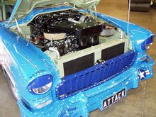
One difficulty was concerned with the installation of the Kugelfischer pump. Like the Bosch system fitted to early Porsche 911s, the Kugelfischer, unlike the Lucas system, requires real power to drive it. The unit was finally mounted below the alternator on an elaborate fabricated bracket made from dural plate and driven via a toothed belt which also drives the alternator. There is an idler, incorporating an adjustable tensioner, made up from a pair of ball races to keep the run of the belt tight around the pulleys. A toothed belt is essential since the injection point must be carefully timed. Additionally, the Kugelfischer requires an oil supply and there must be a drain for oil return. The supply is provided by a tee-piece off the oil pressure gauge line whilst the drain is made via a hole bored into the crankcase fitted with a threaded adaptor.

Drawings of pump drive belt arrangements – done after the event I regret to say!

A FIAT Uno Turbo fuel pump controlled by a Lucas regulator provides fuel at 1.8 bar as specified by Kugelfischer.

A pair of throttle bodies was made by Doug Ellis, our very good friend from the Lancia Club. Doug is a superb craftsman toolmaker and made a good job of them – I have a similar pair on my own car. They use the butterflies and spindles from 42mm Solex carburettors; the spindles run in proper ball races unlike the rubbishy bushes on the Solexes. The inlet manifold (a 1600 one) was modified by welding in four tubes, threaded for the injectors. The throttle linkage was another big problem. Working from the original bell crank, it was necessary to arrange for a long rod to pass down to the Kugelfischer pump to control the fuel. I cannot quite remember how we solved this one but I recall it involved turning something upside-down!

Next time, the concluding part with more pictures


Saturday, February 24, 2007

A Rare Treat

The rightfully proud owner arrives for "refreshments"
Note the wet!

Those of you who have visited this blog recently will know that I am currently in "Blighty" attending to a much modified Land-Rover. Despite the title at the top of the page, I shall probably be writing something about this in due course - those who know me will be well aware that motor-car modifications have always been a source of fascination to me.

I am in Suffolk, and as my friend and sometime customer Robert Ely lives quite close, here was the opportunity to sample his amazing Fulvia-powered mid-engined sports car.

A couple of phone calls and today, Robert arrived as arranged at "The Plough" just after one o'clock. The weather had been pretty foul in these parts so poor Robert arrived rather cold and damp - a glance at the car will reveal the realities of Le Mans-style motoring in February in England. The car sounded a little sick when it arrived, but at that moment the priority was suitable refreshment and luncheon.

These important matters having been dealt with, we set off back to the house where in my Land-Rover client's warm and spacious garage, we could investigate. I was determined to put matters right since I wanted to experience the car, the ride home being "hiccupy" to say the least.

Engine cover up ready for examination

I expect that Robert will forgive me for telling you that he confessed to having "fiddled" with the carburettors somewhat, but I was convinced that the problem lay with the ignition system. Obviously, the clue lies in the rainwater that can be seen in some of the pictures. Sure enough, the distributor cap had plenty of moisture inside, as did the rotor arm. Surprisingly despite the cam cover being rather exposed, there was no water around the plugs - a common Fulvia problem.

The exposed cam cover may be seen in this picture;
this will be protected by a cowl at the front

I cleaned and dressed the rotor arm carefully and added a squirt of WD40 to the cap. On starting up it was obvious that things were a lot better, although not right. I therefore turned my attention to the carburettors. The special tools I have for this job are attached to my head: my ears.

Five or ten minutes with a screwdriver sufficed. I was impressed with the throttle response which I believe is largely due to the very nice exhaust manifold and the vastly better air filter.

"Road test" I said.

So off we went. Mercifully the rain held off, although I soon became quite wet owing to Robert's aerodynamic modifications... The engine sounded excellent and the car is fast - very lively indeed; with probably about 100hp and 500kg this is unsurprising! The gearchange is "back to front" but the low weight means that starting from rest is easy in 2nd gear. The chassis as far as I could judge, is excellent with a firm but comfortable ride, plenty of grip and good turn-in. Sharp-eyed readers will notice that Robert has now fitted attractive 15" aluminium-alloy wheels with very nice sticky Toyo tyres.

My Land-Rover client was keen for a ride so despite being a rugby fanatic, tore himself away from the "Six nations" on the TV.


Looking slightly wind-swept on his return, "Almost as good as my green Land-Rover" he commented!


The windswept return

This is a very serious motor-car; the especial pleasure for me was to hear that mildly modified Fulvia engine sounding like the thoroughbred it is - right next to my right ear.

Robert showed me some of the aerodynamic developments he has been working on, including special venting for the radiator at the front, and a diffuser at the rear.

There is more to come (including a paint job); I shall keep you all informed.

Monday, February 19, 2007

Hey Doll...

“Hey doll, can I borrow your frame for the struggle?”

This 1950s/60s American “beat” dance invitation is my eccentric introduction to a story concerning the horrors of Fulvia front hub bearing replacement.


Q. Why are these men struggling with a long pole?
A. Because this time, a ¾” impact gun was not enough!


The Lancia Flavia and its descendent, the Fulvia were, it must be said, very well and indeed elaborately and expensively engineered. A splendid example of this is the hub bearing. A massive double deep-grooved ball race, this item is well known for often outlasting the car. It has been said that if water does not enter the bearing it will last indefinitely. Certainly on my own car I have a noisy rear bearing; there is no play at all, it is rust that is causing the noise. This bearing I am certain is an original and therefore forty years old! At Evolution Engineering, we used to recover the bearings from scrapped cars and strip them to check condition. Usually there was nothing wrong with them, so we used to rebuild them with synthetic grease and they were as good as new; I have two of these on my car.

However, despite the above, for one reason or another they do have to be replaced from time to time, and it’s a grim business. In this article I propose only to look at the front bearings.

The Fulvia’s (and Flavia’s) front hub bearings are retained in the hub carriers by means of a very large (97mm) castellated ring screw, shown (regrettably a rather dirty – but realistic - example) in the picture below. It is tightened to something like 20 Mkg - about 150 lbs/ft, and in accordance with Lancia’s crazy policy, without any lubrication (I don’t care what you say – I think that this is insane). Given the very fine thread over such a large diameter and the fact that it is usually only after many years that the bearing must be changed, it is not difficult to imagine that unscrewing this ring screw is unlikely to be easy to say the least. Lancia was obviously concerned that it might unscrew itself (absolutely no chance) and so with the thoroughness for which the company was famous, it was locked in place with a spring – the green arrow in the picture indicates the “tongue” at the end of the spring which locates in one of the holes bored in the hub carrier thus preventing the ring screw from unscrewing itself…


The famous front inner ring screw. The shiny part at the centre
is the inner race of the bearing


To replace a front hub bearing the procedure is as follows (see below for tool list):

1. Jack up car, remove road wheel. Support the vehicle on axle stands and chock the rear wheels


2. Undo outer bearing ring nut (nuts and vernier plate for S1)


3. Undo inner driveshaft bolts; remove driveshaft


4. Dismount brake caliper and tie up out of the way


5. Disconnect steering ball joint thus allowing hub to turn to provide sufficient access.


6. Remove locking spring and unscrew inner bearing-retaining ring screw


7. Insert “tool nut” (picture of tool nut below in Tools section) and mount special puller to hub and extract hub from bearing. (Note: sometimes the hub can be removed using two large pry bars or levers). Examine the hub carefully. If there is damage on the part that fits into the bearing then the hub should be replaced; repair is possible but would be very expensive I think.


8. The bearing may now be “drifted out” with care from the hub carrier. If “drifting” doesn’t work, then the bearing may have to be pulled/pushed out using either the tool nut and parts of the special puller or a long bolt and nut with suitable spacers and washers.


9. Clean the carrier carefully and with a little oil, fit the new bearing. Ideally, a suitable drift of about 90mm diameter will be available to push the bearing, acting on its outer race; do not act on the inner part as this can cause the bearing to “dismantle itself” as you will probably have found when removing the old one!. Once the thread is visible, the “Tool Nut” may be used to push the bearing home.


10. Clean the inner ring screw thoroughly, ignore Lancia’s instructions and coat it with “Copaslip” or similar so that if there is a next time, life will be a little easier! Tighten the screw – very tight - but so that the spring retainer will locate in one of the holes provided – usually it lines up OK.


11. Reconnect the steering joint


12. With light oil or WD40 or similar, introduce the hub into the bearing; gentle pushing with slight side-to-side movement is normally all that is necessary to push the hub into position. Great care must be taken since quite often the inner race will fall out and it is a pain to replace it since the rubber seal will have been disturbed. Don’t forget the distance piece which often falls out of the hub/disc assembly. It occurs to me that there might be an advantage in mounting the driveshaft first, since the outer CV joint will act on the inner race and perhaps prevent it from becoming dislocated. However I have never tried this.


13. Next, refit the driveshaft. Coat the splines with Copaslip or similar. Be sure to check the alignment of the splines (CV joint/hub). If all is clean then it should be possible to push the shaft through so that the thread at the end of the CV protrudes so that the ring nut may be started. You can then fit the six cap screws that secure the inner CV to the gearbox flange Do not forget the inner distance piece (S2/3 cars and 2000s only) which mounts between CV joint and the flange


14. Refit the brake caliper


15. Fit outer ring nut(s). This should be tightened to 27 – 33Mkg – or just lean on a four-foot (1.3 metre) piece of tube! There is often a need to adjust slightly on S1s to allow the vernier plate and dowel to line up properly. On S1s the outer locking ring nut is torqued to 7Mkg – say 53lbs/ft. “Stake” the ring nut.


16. Refit road wheel.


Fairly straightforward eh?

No it isn’t. The problem for the private owner (and garagistes who don’t know Fulvias) apart from having all the necessary tools is actually undoing that inside ring screw - and not just private owners. The picture at the top of this article shows what we had to do on one Fulvia, where the ¾” drive air gun was unable to shift the screw. A gun of this type can manage perhaps 80Mkg (800Nm or 600lbs/ft) or more of torque whilst simultaneously hammering…

In the picture we see two chaps leaning on a long steel tube, whilst the third is doing his best to keep the tool engaged in the castellations of the screw. There was a fourth person present, who took the picture – this was me. We always did this on tricky jobs to show the customer why the task had taken as long as shown on his invoice! Incidentally it was fortunate that we had two tools – one (with a ¾” drive socket welded to it) may be seen in the picture, the one we used accepted a very strong tommy bar.

After a considerable amount of straining and swearing, there was a loud bang. We thought the tool had broken, but in fact the screw had finally moved.

In extremis I suppose that after copious soaking with penetrating fluid it might be possible to shift the screw with an air hammer, but it is difficult to use these without damaging the work-piece.

In conclusion, I have to say that I cannot imagine any simple solution to the front (or rear) wheel bearing job on a Fulvia or Flavia. Probably the best way out would be for specialists to offer hub carriers (for the front) and hubs (for the rear) with new bearings fitted, on an exchange basis, but removing the hub carrier at the front is another difficult job in itself. Perhaps one day I’ll write a few words on this subject!

********************

Tools
(Apart from the obvious spanners, punches etc.)
Ball joint separator (for steering arm)
Drifts for bearing removal and fitting
Ring nut tool for outer CV retaining ring nut(s)
Ring nut tool for inner ring screw – and ¾” drive impact gun and good compressed air supply
“Tool Nut”
Special two-way puller

I shall add some pictures of special tools in the near future

Sunday, February 18, 2007

Sorry again

Although I am away fom home (I am in England) I came well prepared, with articles ready topost up on my USB clé.

Unfortunately for some reason, today at least I cannot post pictures.

I will try again soon.

Friday, February 16, 2007

Matt

As I am in England, I have found out that Matt is on holiday - hence the absence of the cartoon.

I at least await his return eagerly.

Wednesday, February 14, 2007

A couple of things

Thanks to those who have commented so far on my "Developments" series - let's have some more.

And I remind you again that I am available from next month to work on your Fulvias (I am in England at the moment doing a modified Land-Rover).

And sorry for the Matt cartoon - not my fault - I await an improvement

Paul

Saturday, February 10, 2007

More on Les Chats

" Il y a des milliers d'années de cela , les chats étaient vénérés comme des dieux.Les chats ne l'ont jamais oublié". Anonyme

Roughly: "For thousands of years, cats have been venerated like gods. The cats have never forgotten it" Anonymous

Source: Here

Fulvia Developments - Part IX

Attenzione! Officer present!

The previous articles endeavoured to offer some practical suggestions for Fulvia engine development. They were meant to provoke thought rather than to provide all the answers.

Now I propose to wander into the land of dreams, the place where the lottery win finally came and where the budget is no longer a factor, a place where the ale is real and good and cheap, where there are no speed cameras or traffic wardens, where all Fulvia spares are available off the shelf, where the women – oops! I was getting carried away...

The suggestions I make here will horrify many traditionalists, but I don’t care; these ideas are the results of hundreds of hours of thought and discussions in pubs… They are mostly intended to address some of the limitations I pointed out when I started this series. I hope at least they are interesting.

I would first set out to mount the engine vertically. This is possible, I know because I once “mocked it up” - the bonnet would just shut. I would scrap the original crankcase; it is structurally far too weak and there is a distinct lack of support for that all-important centre main bearing. I would have a new one machined from a block of suitable aluminium alloy such as HE15 or 30. All the main bearings would be fully integrated into the structure; the caps, a precise fit into the crankcase, would be arranged in a one-piece “ladder” and cross-bolted. There would be a dry-sump installation, with two scavenge and two pressure pumps – one of the latter being solely for the centre main and its associated circuits. The piping could be external.

I would probably opt for a different bore and stroke from original; of course this would have to be drawn up, but probably around 85mm x 70mm to give 1589 cc. This would provide an additional 7% of piston area for about the same capacity as an original 1600. I would have the block cast in aluminium with Nikasil coated bores. There would have to be a special crankshaft of course; this would have a 60mm diameter centre main bearing since the original has insufficient area; the crankshaft would be made from EN40B or 40C steel and nitrided to 0.040” (1mm). I would arrange for a ball race on the other side of the timing sprocket to provide proper support for the front of the crankshaft. Pistons would be as light as possible and the rods would be titanium to improve balance by reducing reciprocating weight.

Lucas fuel-injection mounted on a 1600 engine

It would be too complex to make a new head, so I would bore out the ports and have aluminium tubes pressed in to seal them. I would move the two LH rear mounting bolts to allow for better port diameter (and probably the two RH front ones). I would consider reducing the included angle between the valves which would be larger, probably 42mm and 38mm; this would mean a great deal of welding and machining and also special rockers – the camshafts would be special anyway. The inlet valves would be of titanium and I would use titanium valve caps. Dual ignition would be nice to have but probably impossible to arrange. The vertical installation of the engine would allow a straight inlet tract to accept the throttle bodies. I would continue with the Lucas injection, but this would be mounted at the rear of the head, driven from the inlet camshaft – the vertical engine installation would allow room for the metering unit to clear the cross member that contains the front spring (which would be composite instead of steel or possibly not there at all!). To provide more room around the engine I would mount the alternator on the back of the gearbox. In fact there would probably be a six-speed dog clutch ‘box with limited slip differential. The vertical engine would allow plenty of room for a proper exhaust manifold which would be developed on the dynamometer together with the fuel injection calibration and ignition curves.

The aim would be around 190 hp at around 7500 rpm with the engine safe to over 8000… These would be very expensive horsepower indeed when one considers that 180hp are relatively easily extracted from the 8-valve Lotus-Ford 1558cc twin cam engine that is older than the Fulvia 1600 in design terms, a fact that almost takes us back to the beginning of this series of articles.

My thinking is that all the modifications listed above could have been done in 1970; I believe though that I would be unable to resist installing digital programmable ignition – the alternatives are simply inferior.

I should add that I have similarly radical ideas for the rest of the car in my dreamland. Would it still be a Fulvia? I don’t really know. In the end, it all depends upon how you define “Fulvia”.

To me it would be.

I hope that you have enjoyed reading this series - I look forward to comments and criticism.

A pair of much-modified Fulvias at a Goodwood track day

Photo: Morgan Jones

Fulvia Developments - Part VIII

Well, this large project is now drawing to its conclusion ...

This time more on the engine's mechanicals and one or two other bits.

Cylinder bores should be finished with a “Flexhone” tool. This superb device that looks so simple (some people call it the Christmas Tree) provides a wonderful finish and reduces the need for running in to an absolute minimum. Piston rings should be treated this way too to provide a 45-degree cross-hatch finish.

A 1600 block showing the fine “Flexhoned” finish

If you are rebuilding using an un-rebored block then check the piston clearances before fitting the rings and select the pistons for the optimum clearances for each cylinder

The oil pump is another component that must be carefully checked. Maximum clearance between the rotors as specified is 0.12mm – about 0.005”. I know that the pumps work fine though even with 0.20mm (0.008”) clearance but this is not ideal. Precision rebuilt pumps are available from Huib van Guernink at http://www.viva-lancia.com/ on an exchange basis.

This is a good opportunity for me to let off a bit of steam about oil pressure, always a popular topic. So many people seem to think that the higher the pressure the better. This is nonsense. 65lbs/sq. in. or 4.4 kg/sq cm. is plenty – and it was good enough for the F1 V8 BRM… In fact the Lancia factory specification is 4.0 – 5.0 kg/sq. cm. (57 –71lbs/sq. in.) at 4500rpm and 90 degrees, with just 0.4 – 0.5 kg/sq.cm. (5.7 – 7.1 lbs/sq.in.) at idle at the same temperature; Lancia obviously agreed with BRM! Running higher pressures wastes power, wears the oil pump and heats up the oil unnecessarily. Do not rely on the standard gauge; usually these are pretty inaccurate and only suitable as a guide. Better to fit a proper mechanical gauge.

Most Fulvias are fitted with a fixed oil pressure relief valve, so no adjustment is possible without modification. It is not uncommon to find an engine with higher pressure than normal (when checked with a proper gauge of course). This can be due to someone who, having found the little oil sprayer at the front of the crankcase to be broken, has blocked up the outlet with a self-tapping screw, a good solution but one which will raise the oil pressure, especially at low engine speeds. High pressure at high engine speeds will be due either to a malfunction of the relief valve or perhaps restrictions in the system – maybe gunge collected in the crankshaft, which should of course have been cleaned out!

Cooling System

The standard Fulvia radiator is not particularly good; it is also very heavy. If a suitable aluminium replacement can be found I would suggest that it is a good idea to install it.

The thermostat is specified to allow the engine to run at 70 deg centigrade (158 F). I believe that the engine will make a little more power if run at a slightly higher temperature. I do not think that screw-in thermostats are easily found other than in the original value. One option is to fit a hose mounted unit (in the top hose of course). These are available in a variety of values; I suggest 80 – 85 deg. as being most suitable. The standard electric temperature gauge is quite accurate and may be relied upon.

S1s benefit from removal of the beautifully-made but noisy and wasteful mechanical fan. I have no figures but I would not be surprised to learn that the fan might cost as much as 2 – 3 hp at full speed. Furthermore, the action of the fan slows down the warming-up process which increases engine wear. An electric unit should be fitted, arranged to switch on at about 95 deg.

One other option would be to do away with the water pump. I recently saw a hill climb car here in France that used an electric water pump found on a Renault bus in a scrap yard. This would be controlled by a thermo switch and relay just like the cooling fan and I believe that more power would be saved and warm-up time further reduced.

Crankcase Breathing

I have mentioned above and elsewhere that the breathing arrangements on the Fulvia are inadequate. It was no accident that many of the works cars had an additional breather fitted to the cam cover. As I remarked in the article about the mid-engined special, I know of a case where a modified 1600 engine had its output increased by 5 hp through the fitting of a dry-sump system.

The little oil filler “pot” contains some sort of steel wool which rusts and finds its way around the engine. At Evolution we used to cut them open, remove the rubbish inside and replace it with stainless steel pan scourer material and weld the unit back together. One modification I considered was to fit a small pump that would positively ventilate the crankcase; short of a proper dry-sump installation, I think that this might be the best approach.

Well, that concludes my eight-part series on some thoughts about the Fulvia's engine and how it may be developed.

Well - not quite: there is Part IX...

Thursday, February 08, 2007

More Light Relief

This picture is entitled "Death wish kitty"

Source: here

Fulvia Developments - Part VII

Here we are again - this time looking at some mechanical aspects.

Other Engine Work

All the preceding sections covering modifications quite naturally took the assumption that an engine would be in good order before modification. Increased power and torque will quickly “find out” a tired engine.

Once again, standard practice applies here.

For best performance, mechanical losses must be reduced to a minimum. One must be realistic of course and I doubt that many would wish for example, to polish their crankshafts down so that bearing clearances were at or above the maximum.

A 1600 crankshaft, clean but awaiting polishing of the journals

Nevertheless, attention should be paid to all running fits. You probably know that the crankcase must be bolted to the block and correctly torqued down before the main bearing caps are tightened to specification. The crankcase is very – even pathetically - weak and in the past, I have had to reject a number of 1600 crankcases owing to distortion: on tightening the main caps I found that the crankshaft would not turn freely. The crankshaft itself should also be checked in a lathe with a dial gauge to ensure that it is true. Usually with Fulvia engines the crankshaft nearly always seems to have a little “stiction” when one attempts to turn it by hand. One engine I built for a Fanalone had a lovely free-turning crankshaft and the engine spins up very well. The engine must have had a one of those rare “good” crankcases.

Never forget that these engines are old! The connecting rods are frequently oval at the big end. To check this aspect, torque up the big end cap (without the bearing shells of course) and check for roundness with a bore gauge. If the aperture is “out of round” significantly (say more than 0.0015” – 0.038mm or even less) then you do have a problem. The problem is that nothing can be done about it realistically owing to the serrated finish on the cap faces although it is worth trying different torque settings within the specified tolerances – or even slightly beyond - as this can sometimes result in an improvement. With flat faces of course as found on many other engines, the faces can be machined and the rod bored round again. If the ovality is not addressed, then bearing trouble will be the inevitable result I am afraid.

If you do manage to find a good set of rods, then have them balanced end for end and have the pistons balanced too. The factory specified a 4-gramme tolerance for pistons; this is not quite good enough – 1 gramme is good and less, better! Consider that a piston and rod which at rest weighs say 700 grammes, probably weighs about two tons at 6000 rpm at the top of its stroke (I read this in a book somewhere). That means it weighs 2857 times more that it does statically. Of course errors are partially compensated for by the adjacent piston which is at the bottom of its stroke, but study of reciprocating engines will show that all is not equal and opposite so it’s best to balance thoroughly.

Given the age of the parts, it is quite a good idea to have the rods shot-peened although I have never heard of a Fulvia rod breaking, nor have I ever met anyone who has! I suppose that I should add that the works did produce a special rod for the 1600 so I imagine that they had rod trouble at the very high revs that were used on the low-geared rally-cars. The part number was 2276699 – good luck! The bolts should be removed and peened also. For 1300s, 1300HF bolts are superior (they are of a similar design to the 1600 ones) and can be obtained from Cavalitto.

Bearing clearances should be checked on assembly: “Plastigage” is an excellent product for this job and easy to use. If the clearances are on the tight side, then have the crankshaft polished as necessary.

One small improvement worth doing and standard practice in “blueprinting” is to improve the oilways. Looking at the oilways behind the main bearings, you will see that the outlets have sharp edges – i.e. as drilled. These should be radiused; this will improve flow and slightly reduce the work that the oil pump has to do.

Next time - more mechanical stuff

Evolution Exhaust

Recently one of my customers contacted me after reading this blog and attached a couple of photos of the manifold mounted on his engine.

I have posted it with his permission as it should be of interest to my readers.

Photo: E. Starckmann

Saturday, February 03, 2007

Fulvia Developments - Part VI

Fuel System

I have not a great deal to say about this important aspect, since choice is so limited for the Fulvia – at least if one wishes to preserve a “period” quality. The best solution technically would be full digital engine management with throttle bodies, fully programmable, and which would include the ignition system. With this type of equipment, rev-limiting and traction control are possible and the whole thing can be set up quite quickly on a rolling road. However, many would agree with me that this sort of equipment doesn’t belong on a Fulvia.

So for 99.99%, “fuel system” means carburettors and for most, Solexes (ugh!). The Solex carburettors fitted to Fulvias were poor quality and now after more than 30 years minimum, are frequently worn or rather, worn out. Since Solex went bankrupt years ago (sadly after the Fulvia and not before) parts are not easy, although overhaul kits are not hard to find. Those who have modified their cars will need to alter the jetting. Main jets can be bored out (drills in 0.1mm steps are easily found) whilst air correction jets, which will normally need to be reduced in size, can be soldered up and re-drilled. And don’t forget that with the absurd Solex design, the carburettors must be removed in order to change the main jets, not very practical for rolling-road tuning sessions.

The standard air cleaner arrangement is very restrictive. The best solution is to cut out all the metal inside the cover, weld up the hot air flap and cut back the inlet pipe to accept a piece of hose into which a modern cylindrical air filter may be fitted. The filter should be mounted to pick up cold air somewhere behind the right-hand headlamp. I performed this modification on a 1600 and the owner complained about an enormous flat spot at about 3000 rpm. Changes to the air correction jets cured the problem after which the car went better than ever, and proved that my view about the restrictiveness of the air filter was correct.

Some Fulvia 1300 owners are fortunate to have the vastly superior Dell’Orto DHLB 35 carburettors. These are proper quality, rare, expensive and worth it. I do not agree with many who consider them to be a satisfactory solution for the 1600 as they are too small in my view for proper top-end performance; what a pity that Dell’Orto didn’t make a 40DHLB! The flat spots many experience with the 42mm Solexes (on 1600s) are mostly caused by wear in the spindle bearings and other problems rather than any fundamental shortcoming in specification.

The other route for the better-heeled is to opt for Weber DCOEs or Dell’Orto DHLAs as used on the factory cars. These are much larger and require either a special manifold or a suitable adaptor that fits to the original component. These manifolds are produced but most that I have seen are poor quality and one I had to install would not even fit the car until I had filed and ground large amounts from various surfaces. And then I found that the casting was porous – and the owner had paid £300 for it. Disgraceful. The nicest solution that I have seen was the adaptor fitted to the 1972 Monte-Carlo winning Fulvia – “No 14”. This attractive piece was designed, I believe, to accept the 48mm Dell’Ortos fitted at the time, but look closely at the picture and you will see that the car is now fitted with 45mm Webers. 40 or 45mm carburettors are readily available with 45s being the most popular choice. However, I have driven a 1600 fitted with 40mm DCOEs and I must say that it went very nicely, with noticeably good torque.

The excellent adaptor manifold fitted to Sandro Munari’s famous No 14

One problem with using these large carburettors is that they leave little or no room for a cold air box and all the installations that I have seen draw hot air from behind the radiator thus reducing both volumetric efficiency and effective octane rating (hot air is “nearer” to detonation than cold air). Some works cars had curved rearward-facing trumpets which I presume were an attempt to tackle this problem

One carburettor idea that appealed to me was to use four 40mm Amal or Kehin motor-cycle carburettors. Organising the throttle linkage would be challenging to say the least and the carburettors would be expensive, but I like the idea of a slide rather than a butterfly and I know that some racers (though not with Fulvias) had considerable success years ago with Amals.

A 1300cc fuel-injected Fulvia engine with slide throttles
Photo source unknown

The final option is to use period fuel-injection equipment. And despite the fact that I love the Lucas system on my own car and also that I was involved in arranging a Kugelfischer system on another Fulvia, this approach can hardly be recommended as a realistic option – except for the very determined. Carlo Stella’s Competizione shows what can be achieved with proper development.

After all, I realise I wrote rather a lot - ah well, I do tend to ramble sometimes.

Next time: The first part on engine mechanical aspects.

Thursday, February 01, 2007

Geography Lesson

For those who have forgotten or who have not read all of this blog, I am based in Haute Savoie in France, roughly mid-way between Annecy and Geneva.

My nearest town, although it is very small, is Cruseilles, about three miles or five kilometres from here.

Whilst I am not yet overwhelmed with demands for my services from Fulvia owners (soon I hope!) I am fortunate to live in a very beautiful part of the world. The picture below was taken last Sunday evening, about 15 minutes' walk from home.

For pictures from my walk go here.

Sod the Law!

SMOKING IS NOT ONLY PERMITTED ON THIS BLOG - IT IS ACTIVELY ENCOURAGED

New Internet Speed test

Music and Radio Blog Club

Radio Blog Club, a good friend for a while appears to be in some legislative difficulty...

However, in tribute to its brave effort, I shall leave the existing track on this page (which amazingly still works)

Sadly my Playlist no longer works (hence its removal) thanks to the absurd "Hadopi" legislation in France. Apologies to all.