 Attenzione! Officer present!
The previous articles endeavoured to offer some practical suggestions for Fulvia engine development. They were meant to provoke thought rather than to provide all the answers.
Now I propose to wander into the land of dreams, the place where the lottery win finally came and where the budget is no longer a factor, a place where the ale is real and good and cheap, where there are no speed cameras or traffic wardens, where all Fulvia spares are available off the shelf, where the women – oops! I was getting carried away...
The suggestions I make here will horrify many traditionalists, but I don’t care; these ideas are the results of hundreds of hours of thought and discussions in pubs… They are mostly intended to address some of the limitations I pointed out when I started this series. I hope at least they are interesting.
I would first set out to mount the engine vertically. This is possible, I know because I once “mocked it up” - the bonnet would just shut. I would scrap the original crankcase; it is structurally far too weak and there is a distinct lack of support for that all-important centre main bearing. I would have a new one machined from a block of suitable aluminium alloy such as HE15 or 30. All the main bearings would be fully integrated into the structure; the caps, a precise fit into the crankcase, would be arranged in a one-piece “ladder” and cross-bolted. There would be a dry-sump installation, with two scavenge and two pressure pumps – one of the latter being solely for the centre main and its associated circuits. The piping could be external.
I would probably opt for a different bore and stroke from original; of course this would have to be drawn up, but probably around 85mm x 70mm to give 1589 cc. This would provide an additional 7% of piston area for about the same capacity as an original 1600. I would have the block cast in aluminium with Nikasil coated bores. There would have to be a special crankshaft of course; this would have a 60mm diameter centre main bearing since the original has insufficient area; the crankshaft would be made from EN40B or 40C steel and nitrided to 0.040” (1mm). I would arrange for a ball race on the other side of the timing sprocket to provide proper support for the front of the crankshaft. Pistons would be as light as possible and the rods would be titanium to improve balance by reducing reciprocating weight.

It would be too complex to make a new head, so I would bore out the ports and have aluminium tubes pressed in to seal them. I would move the two LH rear mounting bolts to allow for better port diameter (and probably the two RH front ones). I would consider reducing the included angle between the valves which would be larger, probably 42mm and 38mm; this would mean a great deal of welding and machining and also special rockers – the camshafts would be special anyway. The inlet valves would be of titanium and I would use titanium valve caps. Dual ignition would be nice to have but probably impossible to arrange. The vertical installation of the engine would allow a straight inlet tract to accept the throttle bodies. I would continue with the Lucas injection, but this would be mounted at the rear of the head, driven from the inlet camshaft – the vertical engine installation would allow room for the metering unit to clear the cross member that contains the front spring (which would be composite instead of steel or possibly not there at all!). To provide more room around the engine I would mount the alternator on the back of the gearbox. In fact there would probably be a six-speed dog clutch ‘box with limited slip differential. The vertical engine would allow plenty of room for a proper exhaust manifold which would be developed on the dynamometer together with the fuel injection calibration and ignition curves.
The aim would be around 190 hp at around 7500 rpm with the engine safe to over 8000… These would be very expensive horsepower indeed when one considers that 180hp are relatively easily extracted from the 8-valve Lotus-Ford 1558cc twin cam engine that is older than the Fulvia 1600 in design terms, a fact that almost takes us back to the beginning of this series of articles.
My thinking is that all the modifications listed above could have been done in 1970; I believe though that I would be unable to resist installing digital programmable ignition – the alternatives are simply inferior.
I should add that I have similarly radical ideas for the rest of the car in my dreamland. Would it still be a Fulvia? I don’t really know. In the end, it all depends upon how you define “Fulvia”.
To me it would be.
I hope that you have enjoyed reading this series - I look forward to comments and criticism.

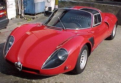
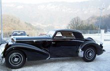
A pair of much-modified Fulvias at a Goodwood track day
Photo: Morgan Jones


10 comments:
Dear Paul, your imagination has no limits! What if.......
But, there's always a but, what makes a Fulvia in my oppinion is the car with the V4 engine (tilted to the left), with leafspring suspension and over 30 years old!
The Fulvia nuova thus, is also no Fulvia but just a very nice executed Fiat with fulvia retro body.
I agree that it is fun and exiting to get the best from the original. Rebuild and blueprint the engine, tweek the chassis but just to make the best of its shortcomings. If you change 90% of an engine for newley designed parts and modify the complete set-up what is the difference with installing a VW VR6 altogether which is already basicly a copied lancia Patent?
My dreams for when I win the lotery are: A Fulvia integrale, for which you can go two ways: One engine in the front and the use of a power take-off gearbox from a Superjolly van to get power to the rearwheels which have to be fitted to an axle with differential. Second idea is to modify the shell to take a subrame with engine in the back and make it a bimotore 4WD.
I personally like the Synthesis designed by Tom Tjaarda and Giacobbi which is a Merak shaped coupé with a Flavia engine ánd it's subrame in the back. Anno 1970!
Well of course everyone will feel differently about these things, but in my "plans" I tried to address soe of the shortcomings of the design - weak crankcase, limited breathing, bearing area and so on. If the Fulvia were not such a wonderful car I would never have bothered! After all I doubt I would do this amount of study on say a VW K70...
And what about your 4 x 4? I have to say it would be very heavy...! Mind you there is a grand tradition in Italy for "bimotores"
Great stuff Paul.
I will hopefully be putting this wisdom to use soon.
However, I'm thinking of forced induction as the most cost effective way for a reliable 130ish bhp (from a 1300 engine).
Supercharging is I guess the only 'period' mod, although is it conceivable that in the late 60's/early 70's one might have been able to dabble with a small turbo or nitrous?
Also, any ideas on superchargers that were around at the time of the Fulvia? A Volumex isn't too far out of the timescale though is it?
I too have thought of a bimotore Fulvia! My lottery Fulvia: lightweight spaceframe built within a S1 shell, 'your' engine front/mid mounted and driving the rear wheels via a period transaxle. Otherwise as many original parts as possible used.
Forgot to add my name!
That was from Robert in case you hadn't guessed.
Well Robert,
Justin dreamed of supercharging for years. But I always said, 1)where are you going to put it? 2) how are you going to drive it? 3) what are you going to do about the four-foot inlet tract?
You see, the problem is that there is no room even for a proper exhaust system. Now, mount the engine vertically and that's another matter. Even on your special I imagine that you will be stuck for space. If you make progress though, let me know!
Good luck,
Paul
Good points. My dry sump pump is in the way! However, I've seen a couple of superchargers that have been turned around and bolted to a cradle that sticks out the front of the engine, and driven by a tricky looking belt system. In a proper Fulvia, the radiator would be in the way, but would fit in mine. In this position I don't think inlet ducting would be too tricky for me.
Hopefully I'll be able to show you soon!
Nitrous would be much 'easier', but I don't think it is 'the right way' to go.
I'm not planning on doing this too soon, so I've got plenty more time for planning(daydreaming).
Robert
Supercharging ... I must confess I had speculated about this, since I do feel that 1300 Fulvias could do with a bit more power and torque.
Paul, you ask 'where are you going to put it'. Well, there's a huge vacant space under the air cleaner box, even bigger if you ditch the stock fan assembly and replace it with a slimline unit in front of the radiator. Something like the smallest Rotrex unit would fit in easily. And there would be no 4 foot inlet tract (!)
Mind you, by the time it was all sorted out, probably including a switch to FI, I suspect less effort and less money could have been spent on a 1600 motor!
Just some idle thoughts ...
Peter
Well, Robert, there you are! Remember you would also have to have some low-compression pistons made, and determine if the centre main bearing could cope with the loads as well...
And you still have to address that very long inlet tract!
Peter,
You still haven't addressed the inlet tract - and in the space you describe there is the dynamo - how will you drive the supercharger?
Thanks
Paul
Well, Paul, I thought I'd better go and look under the bonnet of my Fulvia! Having done all of 5 minutes research (!) I think the main problem is what to do with the radiator, which is of course angled across where a supercharger drive belt and pulley would go. Definitely some form of custom unit would be needed.
As for the supercharger itself, the Rotrex C15, for example, is fairly compact -- 125mm diameter and 141mm long, including the drive pulley. Seems to me that there would be room next to the alternator, although the mechanical fuel pump would have to go, and there would be quite a bit of fabrication needed to come up with a suitable mounting plate.
Anyway, this is all just talk. I must confess that I get a bit annoyed by 'armchair engineers' who are never going to actually do any of their projects ... and I'm certainly falling into that trap myself!
So enough idle speculation for now ....
Peter
Post a Comment