Adsense

A bit of music from the lamented Radio Blog Club

Le Français

Toujours, je suis désolé pour mes amis( et amies) français(es), mais il est difficile pour moi d'écire en français. Peut-être un jour...
S.V.P. regardez ce LIEN
Showing posts with label Part III. Show all posts

Tuesday, April 03, 2007

Land-Rover Antics - Part III

In Part II of this short series, I mentioned that being an ex-military vehicle, the wiring arrangements were rather different from standard. One might add “and how”!

Bill pointed out that the vehicle was fitted with a heated windscreen which had never worked. Indeed the windscreen must have been a costly item: it had very fine (for obvious reasons) heating wires inside the glass running from top to bottom. SII Fulvia owners will recognise the idea as it is similar to the heated rear window fitted to those cars.

The Land-Rover had been an army radio vehicle, so there were many now unused fuse places in the large fuse box – find that fuse!. I knew also that there had to be a relay somewhere – I had already checked the windscreen heater for continuity and it was fine. Bill has a factory workshop manual which showed some details but not all – and no locations!

As is quite common with electrical faults, I spent many hours trying to trace the circuit. This was subsequently found to be even more complex as there turned out to be an internal short-circuit to ground somewhere inside the military wiring harness which is practically impossible to dismantle. Secondly, the control relay – a very special high-current item, which I eventually found buried in a stack of wires behind the instrument panel was controlled by a voltage level unit. Quite ingenious, as this means that one cannot drain the battery since once voltage drops to a certain point, the relay will be shut off. Typically, the damned thing didn’t work!

So I rewired everything behind the instrument panel and ran additional cables to the windscreen heater with an in-line fuse. The ammeter confirmed that all is now well.

I then did quite a lot of the same concerning the heated rear window!

From time to time Bill had experienced a fuel starvation problem. This is nasty on diesel-engined vehicles as of course once there is air in the system the engine stops and that’s it! The installation as I mentioned in Part I was not very nicely done, and this included some rather hit and miss “modifications to the fuel lines not to mention something similar in the turbo piping (more on this later). Bill decided that he would take no chances in future and so he purchased a Facet electric fuel pump to assist the lift pump that is installed in the injection pump unit. I managed to fit this (just) on the bulkhead under the driver’s seat right above the fuel tank, together with a relay and a small fuse box which will provide a useful additional source of current should this be required in the future. There is a reassuring lack of air visible in the piping now.

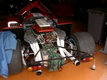
A useful feature on an expedition-type vehicle is an inverter to provide 230v A.C. so that e.g. a laptop computer can be run. The one installed had packed up, so Bill bought a better-quality one which inevitably was rather bulkier. With the amount of accessories fitted space was becoming increasingly in short supply. I devised a neat solution: behind each of the windows is a security grille, so we hung the unit from one of these. The installation which Bill did, is very neat as may be seen in the picture below.


The final electrical task was to persuade the front side lights to work. This turned out to be due to the horrid “bullet” connectors so beloved of British manufacturers – I have experienced vast amounts of grief with these on Jaguars, Austin-Healeys Triumphs etc., etc. As usual one or two had corroded – not behind the lamps where one would expect of course, but once again buried underneath a pile of coloured “spaghetti” behind the central switch panel…

Next time: Turbo pipes, half shafts and other bits and pieces.

Thursday, January 25, 2007

Fulvia Developments - Part III

Some Development Ideas

Having outlined some of the limitations of the design in my two previous articles, I will now offer some suggestions as to how the performance of the Fulvia may be improved. These are based almost entirely on experience of modifying Fulvias on a restricted budget; I have not had the opportunity of tackling a “carte-blanche” project!

Before I begin I should like to set some terms of reference. These ideas and suggestions will be general rather than very specific. Every engine has its own requirements in such areas as fuelling, ignition and cam timing.

Cylinder Head

A gas-flowed 1300 Fulvia head – note the dowels to locate the manifold accurately

As with almost any engine, one should start with the cylinder head. The original fit and finish on the head and its associated components is not perfect – more so on S2s than on S1s of course. All the normal procedures apply and I expect that to many of you they are well known.

Match the inlet manifold to the head and dowel it to ensure accurate repeat fitting. Match the carburettor mounting rubbers also; there is usually a nasty “step” at this point.

Gas flowing a Fulvia is a tough business, first because of the two long ports on each side and second because of the hard, high-quality aluminium alloy used. The usual method requires the use of a good die-grinder with a long “snout” that will allow full access. Tungsten carbide burrs can be used – with care – to “rough out” the valve throats, flap wheels of 60 grit are used for the ports and for the throats but these have to be reduced in diameter before they will enter the ports. A “split stick” with 150-grit paper is used for finishing. Normal practice on the inlet side is to work at the ports until their diameter is about 85% of the inlet valve diameter. This is possible on a Fulvia with standard size valves or even slightly bigger ones. I normally remove all of the boss around the valve guides although one experimental head I did featured a modified boss on the inlet side to provide a “twist” to the incoming charge to ensure better homogeneity of the mixture. I understand it works quite well. Either way, the principal result of this work is greatly improved torque – and I am convinced that much of the benefit comes from the exhaust side. Considerable improvement can be made to the inlet manifold by careful attention. In general I recommend that anyone who fancies trying gas flowing should a) practise on a scrap head and b) read a decent textbook about gas flowing theory – actually in reverse order!

The valve seats should be cut to three angles – for the valve seat itself I prefer 45 degrees to the 30 degrees found on 1300 inlet valves and on both valves on the 1600. A radiused seat is better still (inlets only) and the exhaust seat should be about 1.5mm wide, no more. On standard heads, the seat area can always be considerably opened up greatly improving flow. The inlet seat should be on the edge of the valve and 1mm wide. Careful work on port matching and valve seats and throats probably yields about 75% of the improvement obtained from a full gas flow job.

Seat cutting with a Serdi machine

Larger valves can of course be fitted, but not much larger without drastic changes by which I mean enlarged inlet valve seats. It is a simple job to use 1600 valves in a 1300 head, but of course this represents only a 5.8% increase in valve area; on the other hand every little bit helps.

Important: if you fit larger valves then it is necessary to enlarge the cut-outs in the piston crowns; failure to do this (certainly on 1600s) will result in bent valves and damaged pistons. I have a good procedure for doing this – contact me for details.

Remember that if much larger valves are to be used, the seats will have to be cut deeper and this will mean that the installed height of the valves will be incorrect leading to possible valve float problems unless the valves are correctly specified. Small changes may be corrected with hard washers under the springs. It is however, debatable whether, with the limited port size, any significant benefit will be obtained. In my own engine I have 39.5mm inlet valves and 37mm exhaust valves. The exhaust valves were really a whim as I had some good quality austenitic stainless 1300S inlet valves available and just decided to give the idea a try. Luckily (as it was rather a one-way operation) I detected a small increase in torque in the mid-range and that was it – no money for dyno sessions at the time!

Next time: a look at the valve gear

Sod the Law!

SMOKING IS NOT ONLY PERMITTED ON THIS BLOG - IT IS ACTIVELY ENCOURAGED

New Internet Speed test

Music and Radio Blog Club

Radio Blog Club, a good friend for a while appears to be in some legislative difficulty...

However, in tribute to its brave effort, I shall leave the existing track on this page (which amazingly still works)

Sadly my Playlist no longer works (hence its removal) thanks to the absurd "Hadopi" legislation in France. Apologies to all.