Gearbox
With the engine out of the way, the next task was the gearbox input bearing. It must be said that this is one of the weaker points in the Fulvia’s design and I suppose in this instance, it is Luigi Bosco, designer of the Fulvia’s gearbox who must be held responsible! Indeed the earlier gearboxes, fitted to 1200 sedans and some coupes had an even less adequate arrangement, with a shorter roller race and only one oil seal. Obviously this must have given trouble as a longer bearing and an extra seal were added (an arrangement that still gives trouble hence this section!); I believe that the changeover came at the time of the introduction of the 1300 engine, but I have no easy way of checking this.
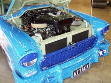
 After removal of the quill shaft: note the oil in the bell housing
First it was necessary to remove the bell housing from the gearbox; this requires beforehand, the removal of the quill shaft, which in turn requires removal of the rear cover of the gearbox, WHICH in turn requires the removal of the rear sub-frame cross member. Not altogether a five-minute job! And since someone had fitted the cross member upside-down, I had to remove the gearbox mounting rubber too. In the end of the gearbox mainshaft you will find a circlip which retains a small steel disc. This covers the end of the quill shaft. A sharp shove on the shaft at the clutch end will expose a circular spring ring on the shaft (at the other end!). When this has been removed, the shaft can be extracted, from the front of course.
The bearing and one of the seals are contained in a steel tubular housing which is a tight fit into the bell housing casting and which are retained in position by means of a spring clip with a “tongue” which passes into a hole bored into the side of the steel insert. The second oil seal is fitted into the bell housing itself, directly below the steel tubular insert. After the spring is removed, the steel insert can be easily extracted, but removal of the seal in the bell housing is a pain: there is no “shoulder” to act upon and in this instance the only way to remove the seal was effectively to destroy it taking care not to damage the bell housing itself. The picture shows some of the parts: the steel housing with the bearing and one of the seals, with the retaining ring next to it. The second seal, and afterwards, the steel housing are mounted in the centre indicated by the red arrow in the picture. The groove in which the retaining spring ring fits may be seen on the exterior of the boss.

After pressing in the new bearing and seal into the steel housing and fitting the bell housing seal, the next job is to refit the steel part to the bell housing. It is of course essential that the holes for the spring clip – in the boss and the steel housing - are exactly aligned as there is not really a second chance, because removal of the housing usually results in damage either to the bearing or to the seals. I find it helpful to draw a line of the bell housing to show the position of the hole. In this case all went well.
Before refitting the quill shaft, I used it as the perfect clutch alignment tool, having already fitted the drastically lightened flywheel.

Clutch fitting using quill shaft for alignment
Driveshafts
With the inner pot-joints (S1s and Flavias only) being secured to the gearbox output flanges, by six set screws, each “squeezed” between the flanges and the ‘box casing, removal of the shafts with the engine in place is a miserable business, especially as the area is normally remarkably filthy. However I was lucky to be working on a clean car with the engine removed. Of course I have the appropriate special tools to undo the ring nuts that secure the outer CV joint; a complex and typically thorough Lancia job on S1s with the inner ring nut (torqued to about 225 lbs/ft – 300NM) the tongued vernier lock ring with its little dowel and finally the outer staked ring nut; it is impossible to imagine this lot ever coming loose. Incidentally this is not unknown on S2s resulting in an intermittent long brake pedal and sometimes, ruined bearings and hubs.
I found that the outer CV joints would not come off the shafts, perhaps through previous damage to the circlips, but the inner ones came off easily albeit with a large quantity of horrid black gloop! All CV joints were in excellent condition with no detectable play whatsoever.
Sub-frame Assembly
Having found loose nuts and bolts in various places, I checked those that were accessible on the sub-frame – again a good idea since the four long 8mm bolts and nuts that retain the front spring were really very loose, and someone had omitted to fold over the tab washers that lock the four short lateral bolts. After correcting these lacunae, it was time to refit the engine.
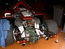
I cannot remember ever having an engine go back in so easily – it just slid in to engagement with the gearbox almost by itself – demonstrating the importance of slinging the unit carefully to ensure the correct angle.
 The engine went in like a dream - I was smiling more a couple of minutes later!
As there was a compression tester available I carried out some cold compression tests, first “dry” and then with a little oil added to each cylinder; this normally shows up ring sealing problems. There was indeed a great difference between the two sets of figures – something like 105lbs/sq in (7 bar) dry and 180 lbs/sq in (12 bar) with oil added. I concluded that there were problems with the piston rings.
On starting the engine I was amazed how nicely it ran – with the oily exhaust port and compression test results I had expected smoke and uneven running, but the motor ran like a sewing machine. And the subsequent road test showed good power and smoothness and again no smoke. I hate to have to admit this but this is a complete mystery to me. The owner confirmed that the car made smoke but it no longer does! And when switched off, the engine stops almost instantly – partially due of course to the light flywheel but also to good compression.
Rear Hub Bearings
The owner had wisely acquired some good stripped rear hubs – I do not own the tool to remove the outer bearing retaining ring nut and in any case, two weeks’ soaking in oil and a ¾” impact gun are usually necessary.
However, I had detected no bearing noise during the road tests, and checking showed that the bearings were perfect; just a faint noise probably from the handbrake pads. The owner expressed his opinion of the CT/MoT man in very “full and frank” language!
With nothing left to do, we set out on a more extended road test. Once again the car ran perfectly, with zero smoke and encouragingly good oil pressure. I was able to drive also and enjoyed every minute; a really good S1 is a true epicurean delight.
 A small break on our road test
 I believe that on departing I left behind me a pretty satisfied customer!
Contact me if I can help with your Fulvia - VAR1016@gmail.com